- Low noise level by guided pins
- Performance factor of 1.5
- Compact design
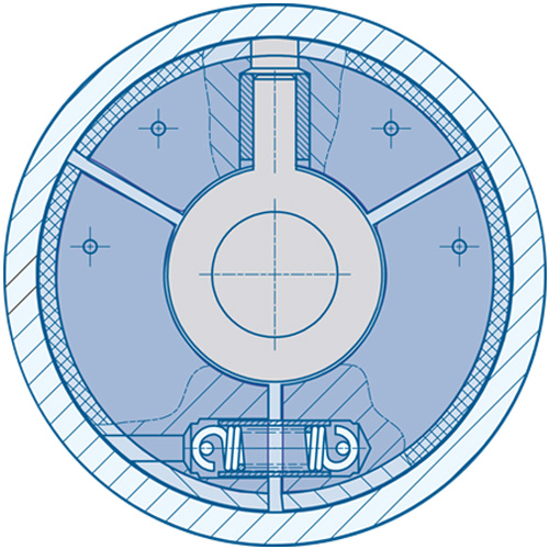
Construction and mode of operation
The cylindrical hub carries three flyweights which are located by and can slide on cylindrical pins . Inside the flyweights there are tension springs which restrain neighboring flyweights until centrifugal force overcomes the spring force. Then the flyweights lift from their seats and the linings on the flyweights contact the inside diameter of the clutch drum. Friction between the linings and the clutch drum allows torque to be transmitted.
- cylindrical hub
- flyweight
- cylindrical pin
- tension springs
- linings
- clutch drum
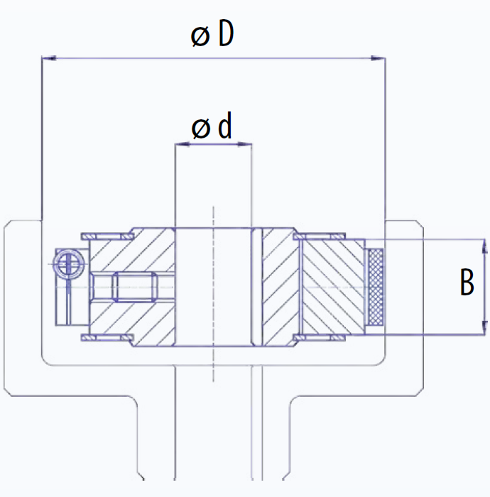
Performance data and dimensions
| Type Number | D [mm] | B [mm] 1 | d max. [mm] | standard bore diameter d [mm] (inch) 2 | Standard rotational speed | |||||
| low | normal | high | ||||||||
| M at nE 750 and nB 1500 [Nm] | recommended motor power [kW] 3 | M at nE 1250 and nB 2500 [Nm] | recommended motor power [kW] 3 | M at nE 1500 and nB 3000 [Nm] | recommended motor power [kW] 3 | |||||
| S04 | 80 | 25 | 24 | 15 (3/4; 7/8) | 4.3 | 0.3 | 12 | 1.6 | 17.5 | 2.8 |
| S05 | 90 | 25 | 30 | 14; 30 (3/4; 1) | 7.5 | 0.6 | 212 | 2.8 | 31 | 4.9 |
| S06 | 100 | 25 | 24 | 20; 24; 28 (3/4; 7/8) | 11 | 0.8 | 30 | 4.0 | 43 | 7.0 |
| S07 | 110 | 25 | 30 | 28; 30 (1) | 15 | 1.2 | 45 | 6.0 | 64 | 10.0 |
| S08 | 125 | 25 | 40 | 20; 30 (1; 1/2) | 30 | 2.4 | 85 | 11.0 | 124 | 20.0 |
| S09 | 138 | 25 | 30 | 17; 30; (1; 1 1/8) | 40 | 3.0 | 112 | 15.0 | 160 | 25.0 |
| S10 | 150 | 35 | 40 | 38; (1 1/8) | 78 | 6.0 | 216 | 28.0 | 310 | 49.0 |
1) The transmitted power increases as the width B is increased.
2) Tapered bores and special dimensions can be manufactured on request.
3) Motor power is calculated using a safety factor of 2.
Final selection of the clutch should be accomplished by SUCO!
d = bore dia.
d max. = max. bore dia.
B = flyweight width
D = inside dia. of drum
M = torque
nE = engagement speed
nB = operating speed